Copyright 2015, 2025 - Alan R. Klase - All rights reserved
Time
flies
when your having fun:
I sold my house in the deep New Jersey suburbs in 2007, and moved to Jersey City. The crystal set environment here is quite different. See: The City Mouse. So it's been a while since I built a serious crystal radio. For a while now, I've had good intentions of building a reproduction of this WWI Telefunken Crystal set. This is a good example of a portable communication receiver from 100 years ago. And, having been designed for short-range communications on the battlefield, it is strictly a medium wave device. The tuning range is 500 to 2000 KHz, making it much more like a broadcast-band crystal set, than the better know maritime radios of the wireless-telegraph era.
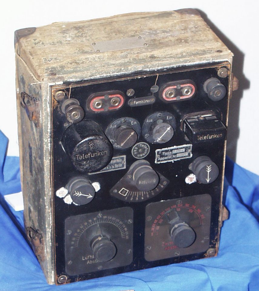

I sold my house in the deep New Jersey suburbs in 2007, and moved to Jersey City. The crystal set environment here is quite different. See: The City Mouse. So it's been a while since I built a serious crystal radio. For a while now, I've had good intentions of building a reproduction of this WWI Telefunken Crystal set. This is a good example of a portable communication receiver from 100 years ago. And, having been designed for short-range communications on the battlefield, it is strictly a medium wave device. The tuning range is 500 to 2000 KHz, making it much more like a broadcast-band crystal set, than the better know maritime radios of the wireless-telegraph era.


This
radio was displayed in the Fort Monmouth
museum..... but now,
it's in here, beside the Lost Ark.
This
radio is associated with Edwin Armstrong, who's unit in France,
1918, did evaluations of captured equipment..
These
Signal Corps blueprints came from HERE.
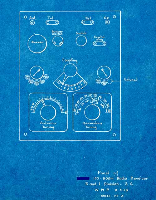

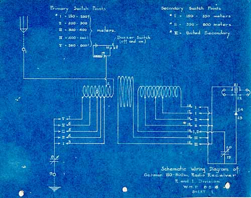
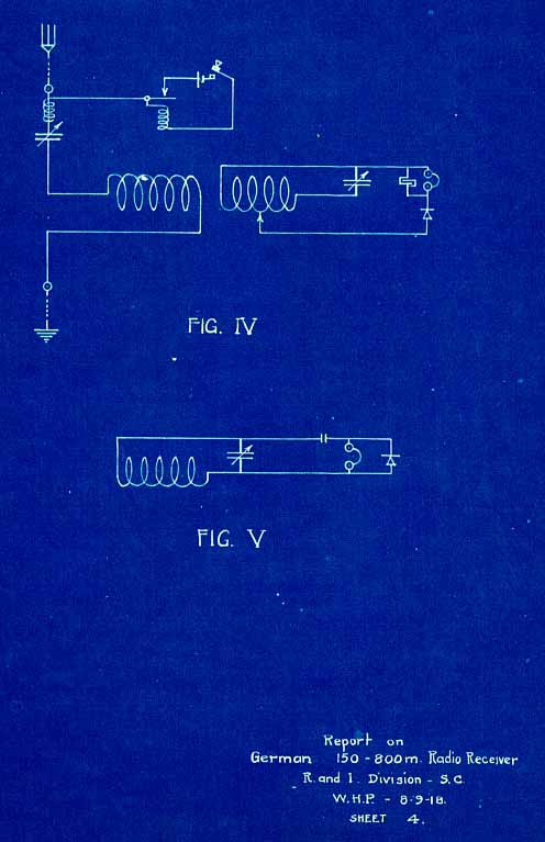
This is one of the earliest radio I know of where the designer was smart enough to tap the detector "down" on the tuned circuit.
I
didn't feel up to an accurate reproduction, so I'm settling for a
similar circuit with a few modern tweaks.
The Breadboard:
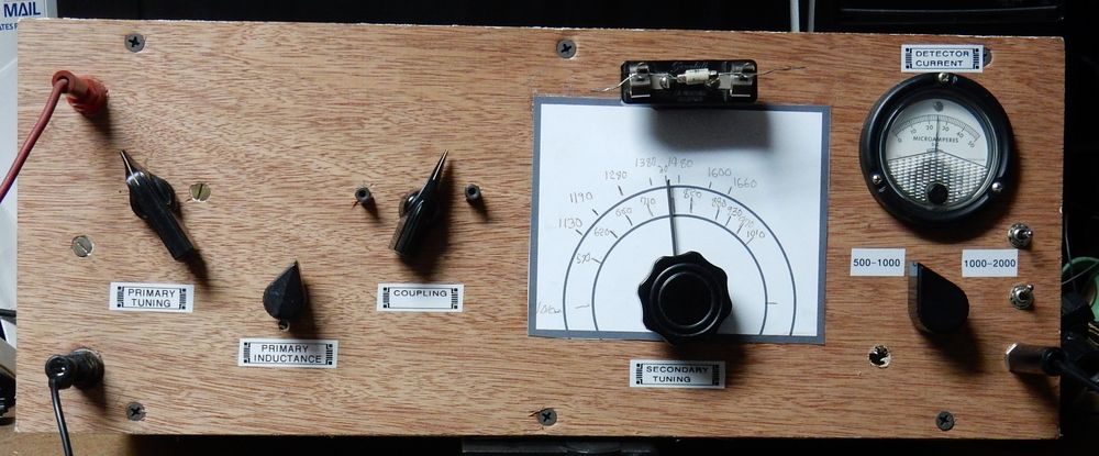
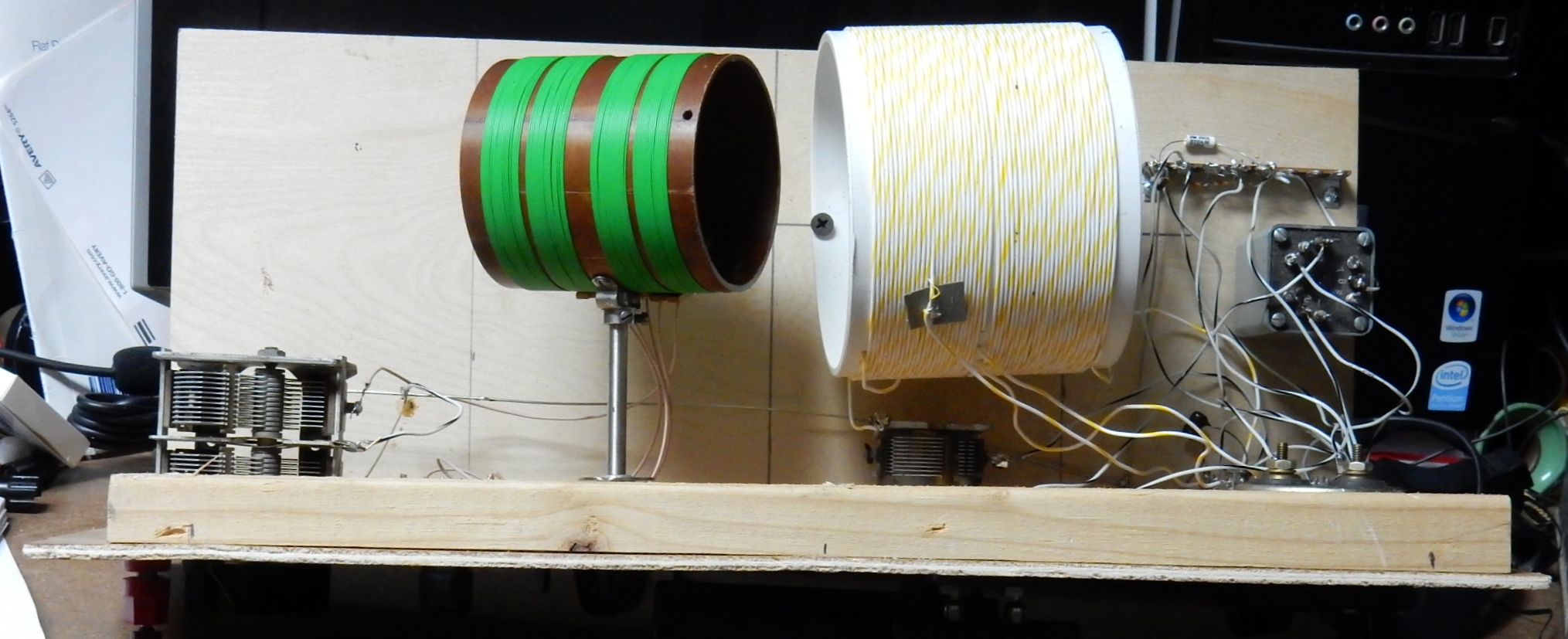
If you're going to build anything nearly this complicated, you need to breadboard it first. I used a piece of 1/4" luan plywood, and a 3/4" base. I added a wooden stiffener to the top of the front panel.

Inside (Final)

Features:
Final Build
 .
.
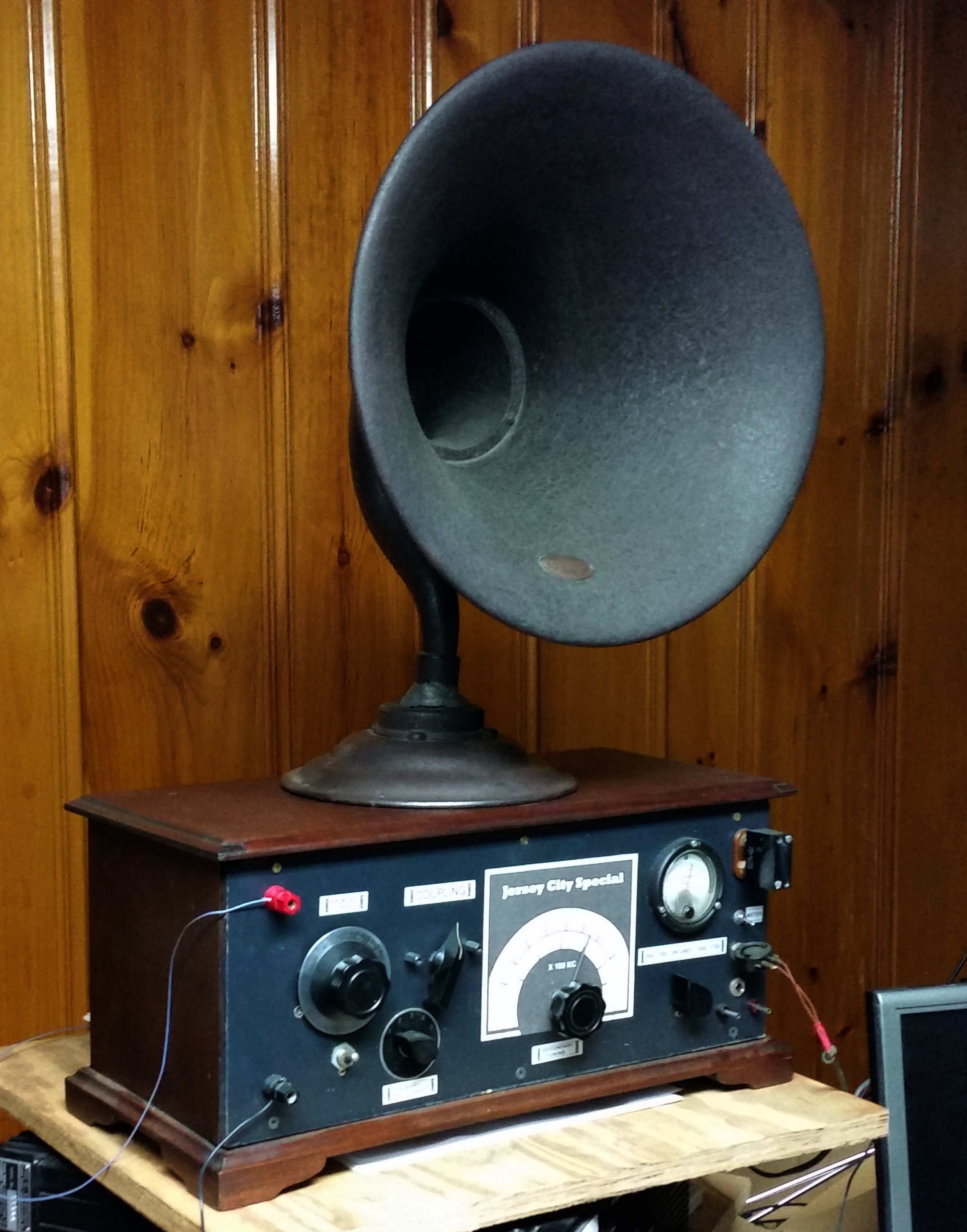
I've been playing the set into an modified Atwater Kent horn with an sound-powered telephone element as a driver.
Horn Speakers
JC Special on the Air into a speaker New 2025
Video of my presentation to the New Jersey Antique Radio System
The Breadboard:
If you're going to build anything nearly this complicated, you need to breadboard it first. I used a piece of 1/4" luan plywood, and a 3/4" base. I added a wooden stiffener to the top of the front panel.


Inside (Final)

Features:
- Classic Double-Tuned Circuit
- The primary tuned circuit can be operated in series or parallel with the antenna-ground system.
- Parallel
better accommodates short antennas.
- Variable Coupling between Primary and Secondary
- The primary rotates via the "Coupling" knob.
- There
are stops to limit the rotation.
- "Contra-Coil" Secondary
- This is a Ben Tongue inspired thing.
- The two windings are in series for the low band, and in parallel for the high band.
- There
is an untuned secondary, in keeping with the original
Telefunken circuit.
- Calibrated Secondary Tuning Dial
- Audio
Transformer
to support Sound-Powered Headsets It's a UTC A-11.
- Detector-Current Meter (50uA full-scale) for tuning and comparative measurement
- In series with the 100K "Benny" resistor for normal measurements.
- Meter shunted by 470 Ohms for strong signals.
- Benny
shunted for maximum meter sensitivity.
- 2nd
Phone Jack for Training Purposes. In fact, that was a
feature of the Telefunken set.
- Using my low (25-feet) ham-radio 80-foot doublet connect as a T-antenna.
- 18 easily-listenable stations using a sound-powered headset.
- Sufficient audio output to drive my 1920's horn speaker with sound-powered driver element on the stronger stations.
- Audio output approximately -10 to -30 dBm.
- For example: WABC, 50KW, omnidirectional antenna, distance = 12 miles.
- Rectified carrier power in the 100K diode load (Benny resistor) = -12 dBm
- Audio
output:
-22 dBm average.
- No sign of any signals from outside the metro area.
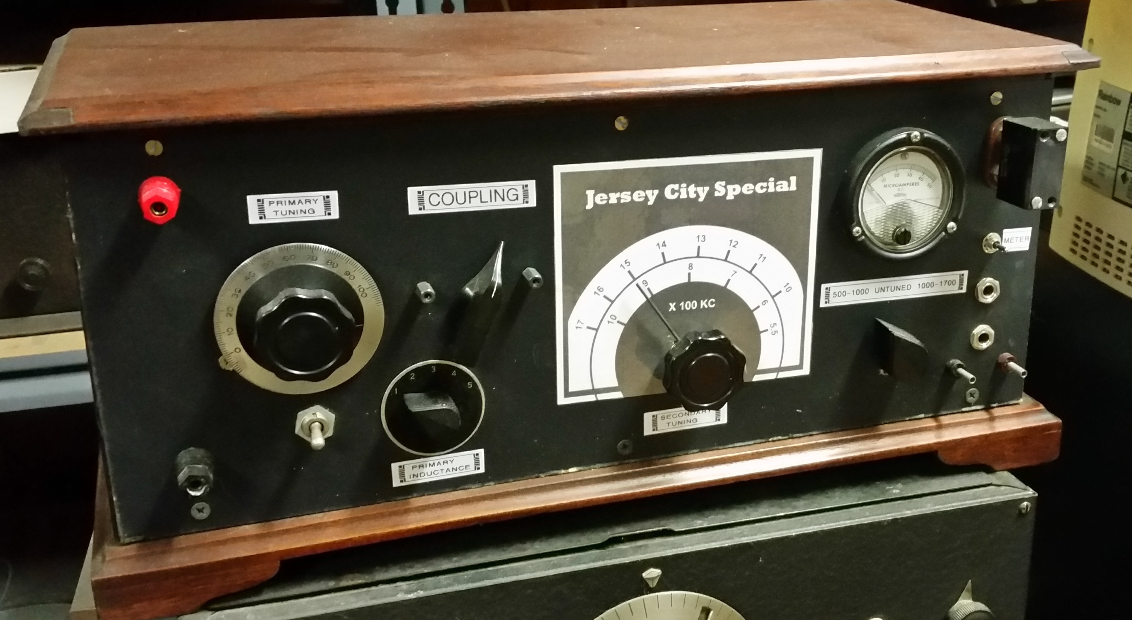
Final Build

- Front panel is 1/8" tempered hard board (Masonite) painted flat back to simulated Bakelite.
- I scanned the penciled-in dial form the prototype, and
used CorelDraw to construct the calibrated secondary dial.
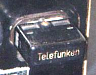
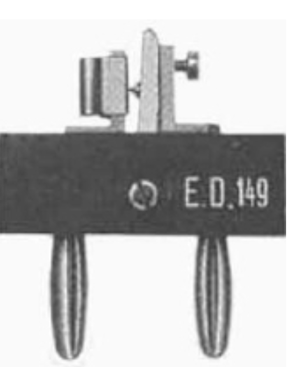
- The detector is a 1N34'ish diode installed in a quartz
crystal holder to ape the Telefunken detector in the German set.

- Cabinet is a vintage piece from the 1920's
 .
.I've been playing the set into an modified Atwater Kent horn with an sound-powered telephone element as a driver.
Horn Speakers
JC Special on the Air into a speaker New 2025
Video of my presentation to the New Jersey Antique Radio System