CRYSTAL SET DESIGN
102
Copywrite 1997,
1998 - Alan R. Klase
- All rights reserved.
INTRODUCTION
Welcome to
Crystal Set Design 102.
It is assumed that you've already completed the 101 level course
elsewhere,
and know, at least, something about electronics in general and crystal
radios in particular. If not, hit the books. The stuff in
your public
library will get you started. The early chapters of
the "Radio
Amateurs Handbook" are especially concise and approachable.
I've been
a little disappointed
at the lack of meaningful crystal set technical information on the web
and in current literature. This is my attempt to at least
partially
remedy this situation. This work is the result of about ten
years
part-time investigation of crystal radios from an engineering
perspective.
Serious development of passive receivers pretty much came to an end
with
the introduction of reliable vacuum tubes around 1920. A lot
of crystal
sets, both commercial and home brew, have been designed in the interim,
but most are mediocre performers. So the mission turned out
to be
one of rediscovering the the secrets of the age when spark was king.
GETTING
STARTED
My approach is to build crystal
radios out of quality
vintage radio parts. They are available in great profusion at
amateur
radio "hamfests" and antique-radio meets (and in my garage).
If you
don't have access to these sources, I'd suggest you start at Radio
Shack:
Buy their Crystal AM Radio Kit, 28-177, for $6.99. This is
actually
not a bad crystal set, and it contains a coil, a variable capacitor, a
germanium diode, and, most importantly, a reasonably sensitive
high-impedance
ear phone. You're also going to need an antenna.
This generally
means wire up in the air. The attic may be the next logical
alternative.
Apartment dwellers may be in trouble unless you're near an AM radio
station,
or can arrange a "stealth" antenna of some sort.. Again, if
you don't
(yet) have a junk box, get Radio Shack's Outdoor Antenna Kit, 278-758,
for ten bucks. Wire has always been expensive, and hard to
find retail,
so keep your eyes open for bargains. Another RS item, that's
almost
indispensable, is a set of mini-alligator jumper cables, 278-1156, 10
for
$3.99. These are how you make temporary "breadboard" hookups
while
experimenting with new circuits. You'll also want
basic electronic
hand tools and a soldering iron.
CIRCUITS

|
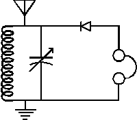
The simplest
radio you can build is just a
diode detector and a headset. With a reasonable antenna and
ground
you will hear the strongest stations, albeit all a once. This
is
not much of a radio. but it will give you some indication that you have
enough signal strength to continue experimenting. |
|
The primary problem
with the above set is that it offers no selectivity. We'll
solve
this problem by building a tunable filter. This will
generally consist
of a coil and a capacitor forming a tuned circuit. Either the
capacitor
or inductor, or both need to be variable so circuit can be tuned to
different
stations. The classic values are 250 uH and 365 pF to tune
the broadcast
band. This is the basic crystal set schematic you'll find
almost
everywhere. It works better than just a diode, but has some
serious
short comings that are easily remedied. |
THE IMPORTANCE OF
IMPEDANCE MATCHING
In a crystal set, all the audio
power that arrives
at your ear drum came from the distant transmitter. If the
transmitter
is hundreds of miles away, the amount of power captured by even a good
antenna is reckoned in nanowatts . At each point in the set
we must
strive to transfer at least a reasonable percentage of the available
power
to the next stage. Perfect impedance matching is not
necessary,
don't fret over a 2 to 1 mismatch, but let's eliminate as many of the
10
to 1 and 100 to 1 mismatches as we can.
SINGLE
TUNED SETS
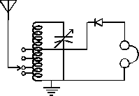 |
In the case of the simple set in
the last example, lets
do two things: Tap the antenna input "down" on the
coil. The
impedances of the antenna and tuned circuit will vary with frequency,
so
it's a good idea to provide multiple taps and a selector switch or
movable
jumper. As a starting point tap the coil at about 5%, 10%,
20%, and
50% of the total number of turns from the ground end of the
coil.
Secondly, connect the detector to the 50% tap. This does two
things,
both of them beneficial: It provides a better match to the
detector
when it's connected to the usual sort of crystal set headphone that has
an impedance of about 10K ohms, resulting in a louder signal.
It's
also reduces the loading on the tuned circuit, increasing it's Q and
consequently
it's selectivity. |
These improvements result in a better
than average
crystal radio. With 50-75 feet of wire up in the air, you
should
hear daytime 50KW stations out to 40-50 miles, and night-time skywave
stations
will come in form hundreds of miles away. This is essentially
the
circuit I arrived at for my Cub Scouts a few years back. (See
The
Den Two Crystal Radio in Crystal Set Projects
published by The
Xtal Set Society) You'll also notice it's almost exactly the
same
circuit used in the Radio Shack set
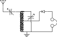 |
Another effective way to match the antenna
to the tuned circuit is to use a variable capacitor as shown in the
drawing.
A cap in the 300-500 pF range is appropriate. Tune in a
station then
change the coupling and retune and see if there's an
improvement.
Some sets have the coupling capacitor in the ground lead instead of the
antenna lead. Electrically it's the same thing, but sometimes
it's
more convenient for mounting and grounding and eliminating hand
capacitance
effects. |
 |
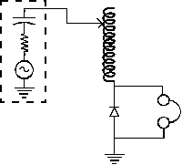
With the previous circuit,
connected to a good sized antenna,
you'll find you can set the tuning capacitor to it's minimum value, or
even remove it completely and still get good performance. To
understand
how this "series tuned" receiver works, I've inserted the equivalent
circuit
of the antenna in the drawing. Any Macroni antenna less than
a quarter
wavelength long appears to be a capacitor in series with a small
resistor,
known as the radiation resistance of the antenna, and an RF voltage
source.
This is almost always the case as a quarter wavelength, even at the top
of the broadcast band, is 187 feet. Our aim is to make as
much RF
current as possible flow from our antenna. When the series
value
of the antenna and tuning capacitors and the inductor are
tuned to
the frequency of interest, the inductive and capacitive reactance's
cancel
out, leaving only the DC resistance of the inductor. This
results
in maximum current flow in the tuned circuit, and maximum voltage
applied
to the detector. A receiver of this sort will usually require
a variable
inductor to cover the entire broadcast band. In such cases, keeping the
detector connected to the optimal point on the coil presents
challenges. |
 |
One classic
variation on the series tuned
receiver, known as the "two-slider tuner", dispenses with the tuning
capacitor
entirely. Instead a sliding contact on the coil varies the
inductance
in the antenna circuit. A second slider connects the detector
at
the best point on the coil. Total inductance should probably
be the
better part of a millihenry. |
 |
Yet another,
historically common circuit, connects
the detector in series with the variable inductor. This is
not such
a great idea from the standpoint of impedance matching, but it is
simple.
Series tuned sets all have difficulties with short antennas, because
their
capacity is low. |
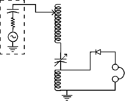 |
Another way to implement the series
tuned set, that improves the match to the detector, is to connect the
detector
and headset across a second coil in the series circuit. For
the broadcast
band, this coil has a fixed value of approximately 80 uH. The
variable
capacitor is optional, especially if the larger inductor is
continuously
variable. |
Single-tuned crystal sets, whether series or parallel tuned,
leave
a lot to be desired in terms of selectivity. Yes, the nose
selectivity
can be improved by increasing the Q of the tuned circuit, but the skirt
selectivity remains hopelessly broad. The obvious solution is
to
use more than one tuned circuit. The point of diminishing
returns
is between 2 and 3 circuits for a crystal set due to cumulative losses
and tuning difficulties.
THE
TWO-CIRCUIT RECEIVER
 |
The classic
solution is the "two circuit"
tuner. The antenna circuit is series tuned by a variable
capacitor
and an inductor, while the detector circuit is connected to a parallel
LC circuit. The amount of mutual inductance, or coupling,
between
the primary and secondary circuit is generally made variable.
This
allows light coupling to be used to obtain the sharpest tuning, while
increasing
the coupling increases sensitivity at the expense of
selectivity.
This is essentially the same architecture used to great effect
in
the communication receivers of the wireless era. If you're
seeking
better performance for your crystal set this increased complexity is
well
worthwhile. |
There are several way to
implement variable
coupling in the two-circuit set. The navy style "loose
couplers"
used a secondary coil that telescoped inside the primary.
Other possible
schemes include variable taps on the low end of the secondary coil,
link
coupling between the two coils, or the use of a small variable
inductance
common to both circuits.

|
Variable coupling
schemes for two-circuit tuners.
ADDITIONAL DETAILS
The primary
inductance will want to have a
maximum value of about 500 uH to reach down to 530 KHz.
However,
a lesser value in needed to reach the 1600 KHz end of the
band.
I've been building coils with five or six evenly spaced taps.
This
lets you tune around for an optimum match to the antenna.
Install a DPDT switch to allow
the primary
circuit to be operated in a parallel-tuned mode: The input
end of
the primary capicator is grounded, and the antenna attached to the top
of the coil. This allows effective operation with short
antennas.
If a non-fixed detector is
used in a double-tuned
circuit, it's a good idea to include a buzzer to generate a local
signal
to adjust the detector. The circuit is a low-voltage
mechanical buzzer,
a battery, a push-button switch, and a one-or-two-turn link to the
secondary
coil. A low voltage relay with it's normally-closed contact
wired
in series with the coil is a good substitute for a buzzer.
HOME


