To maximize volume from headphones or a speaker, measure and use effective impedance for transformer impedance matching. No lab test equipment is neededBy Ben H. Tongue
The magnitude of headphone or speaker impedance varies widely over the audio frequency range, being partly resistive and partly reactive. A 'Fixed Insertion Loss Variable Output Resistance Attenuator' (FILVORA) can be used to indicate the effective average value of this impedance, over that frequency range. The first section of this Article refers to the measurement of mono headphones and individual speakers by using a FILVORA. The second section describes how to use the FILVORA to determine the effective average impedance of each element in a stereo headset. The third section describes how the FILVORA was designed. Section 1. |
|
 |
|
|
|
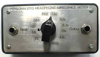
The circuit shown above has a fixed input resistance of 1000 ohms +/- about 5%, no matter what load is connected to the output or where the switch is set. The output resistance at any switch point is about +/- 5% of the value shown with any impedance driving the input. The insertion loss of the FILVORA is 26 dB. Standard 5% tolerance resistors are used. The use of resistors that differ by +/- 10% from the values shown should not have an appreciable impact on performance of this unit. To use the FILVORA, connect a source of audio voice or music to the input jack J1. (I use the output jack of a transistor radio for my source.) Connect the plug of the mono headphone set or speaker to be measured to the output jack J2 of the FILVORA. Adjust the switch for the loudest volume. The correct setting indicates the effective impedance is very broad and somewhat hard to determine. Call it P2. Rotate the switch in one direction from P2 for a small reduction in volume to position P1 (generally a two positions movement), then in the other direction from P2 by two positions to P3. If the volume at P1 and P3 are the same, P2 indicates the effective impedance of the headset. If the volume at P1 and P3 is not the same, increment both the P1 and P3 settings ccw or cc by one position. When you obtain the same volume at the new P1 and P3 positions, you are done. The effective headphone impedance is the calibration indication of the switch at point P2. Sometimes equal volume settings cannot be obtained with switch settings five positions apart. If this is the case, try to get equal volume settings four positions apart. If this is done, the effective impedance is equal to the geometric mean of the settings of P1 and P3. (Take the square root of the product of the calibration readings at P1 and P3.) The effect of source impedance on tone quality. It is interesting to note, that with magnetic elements, setting the switch to a high source resistance tends to improve the treble and reduce the bass response, compared to the response where the source matches the effective impedance of the element. Setting the switch to a low resistance does the reverse. This setting rolls off the treble, and relatively speaking, improves the bass. With piezo ceramic or crystal elements, a high source resistance tends to reduce the treble and improve the bass response, compared to the response where the source matches the effective impedance of the element. A low source resistance tends to reduce the bass and emphasize the treble. Some piezo elements sound scratchy. This condition can be minimized by driving the elements from a lower average impedance source. Here are some practical experimental ways to vary the audio source resistance of a crystal radio set when receiving medium strength to weak signals. A medium strength signal is defined as one at the crossover point between linear to square law operation (LSLCP). See the graphs in Article #15A.
If you are interested in DX reception with headphones and do not have normal hearing, you might want to customize the source resistance driving the headphones. This enables using the 'change in headphone frequency response as a function of headphone driving resistance' to partially compensate for high frequency hearing loss. Input a voice signal and reduce its volume to a sufficiently low level such that you judge you understand about 50% of the words. Readjust the switch to see if you can obtain greater intelligibility at another setting. If you can, this new switch setting indicates the source resistance with which to drive the particular headphones being used to deliver maximum voice intelligibility for your ears. I call this resistance: Personalized Headphone Impedance (PHI). For magnetic headphones, this resistance is higher than the average impedance of the earphones, for piezo-electric ceramic earpieces, the resistance is lower. Two FILVORA units enable one to compare the actual power sensitivity of two headphones, even if the effective impedance the two headphones are very different. A dual unit to do this (DFILVORA) is described in Article #3. Section 2. The effective impedance of hi-fi stereo headphones may be checked with the FILVORA. The effective impedance of the two earpiece elements can be checked by determining the switch position for maximum volume with one of these connections: (1) The sleeve, to the ring and tip in parallel or (2) the ring to the tip. Measurement (1) will show one half the effective impedance of one earpiece and measurement (2) will give a reading of two times the effective impedance of one element. Section 3. To help define the equations used to calculate the the resistor values for the asymmetrical attenuator 'FILVORA' the following requirements were set up:
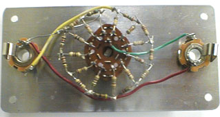
A system of 25 simultaneous was written and solved in MathCad for the values of the 24 resistors. Those are the values (5% resistor series) shown in the schematic. To minimize power loss, the attenuator becomes an inverted L minimum-loss pad at the two extreme switch positions. It is a non-minimum loss T pad at the intermediate positions. The output resistance range of the FILVORA is 10,000 to 1. This establishes the minimum loss. If the output resistance range were 100,000 to 1, the insertion loss would have to be 31 dB. Insertion power loss = 5*log(resistance ratio)+6dB. #2 Published: 07/15/99; Last revision: 06/21/2003 |
|