 | - AN/URC-11
(UHF) and AN/URC-14 (VHF) were introduced in 1954 as replacements for
the somewhat larget URC-4 that operated on both the VHF and UHF
energency frequencies.
- The original versions have 6 subminiature tubes and two germanium transistors.
- The A versions have 5 subminiature tubes and two germanium transistors.
- All operate from the same battery as URC-4.
- It
appears that the miltary's transistion to UHF was well underway.
Consequently, there seems to have been more URC-11's built than
14's.
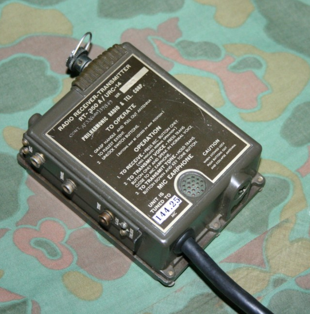
- My unit is serail number 253. Note the hand-scribed U.S. Air Force contract number.
- There are reports that URC-14's, without Air Force contract numbers, were include in commercial airline survival kits.
- Set was originally tuned to 121.5 MHz.
- More info here: http://www.greenradio.de/e_rt285.htm
|
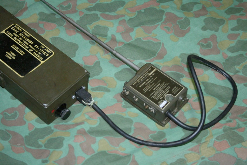 | 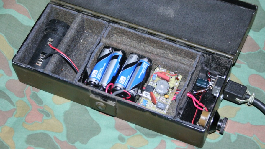
Power
supply was constructed in a surplus CY-1210/U case. Eight
AA-cells power a fly-back converter to supply 100 VDC. C-cell, on left, powers the tube filaments.
|
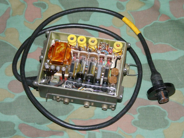 | Interior of the URC-11 is virtually identical to the URC-14. The two transistors are currently in my URC-14. |
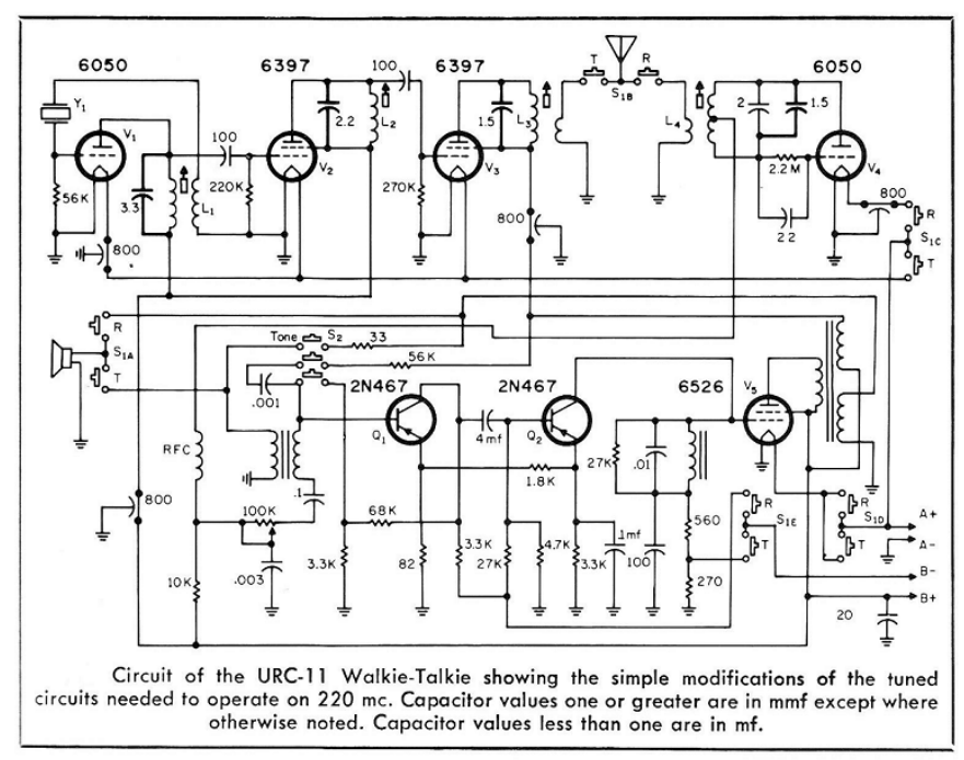
- This is the URC-11 schematic. The URC-14 is virtually identical except for the tuned circuits.
- Crystal, Y1, was 60.75 MHz.
- URC-11 doubles this frequency in V2 and doubles again in V3 for an output of 243 MHz.
- V4 is the super-regenerative receiver.
- Drawing shows caps added to each tank circuit to pull the radio DOWN to the 220 Mhz ham band.
- URC-14 doubles in V2 and V3 is a straight power amp for an output of 121.5 MHz.
- To move the URC-14 UP to the 144 MHz ham band I added no caps, and removed one turn form each coil.
- I'm using a 72.125 MHz 5th-overtone series-resonant crystal in an HC-49 holder from International Crystal Manufacturing for an output of 144.250 MHz, the de facto MRCA official 2-meter AM frequency.
|
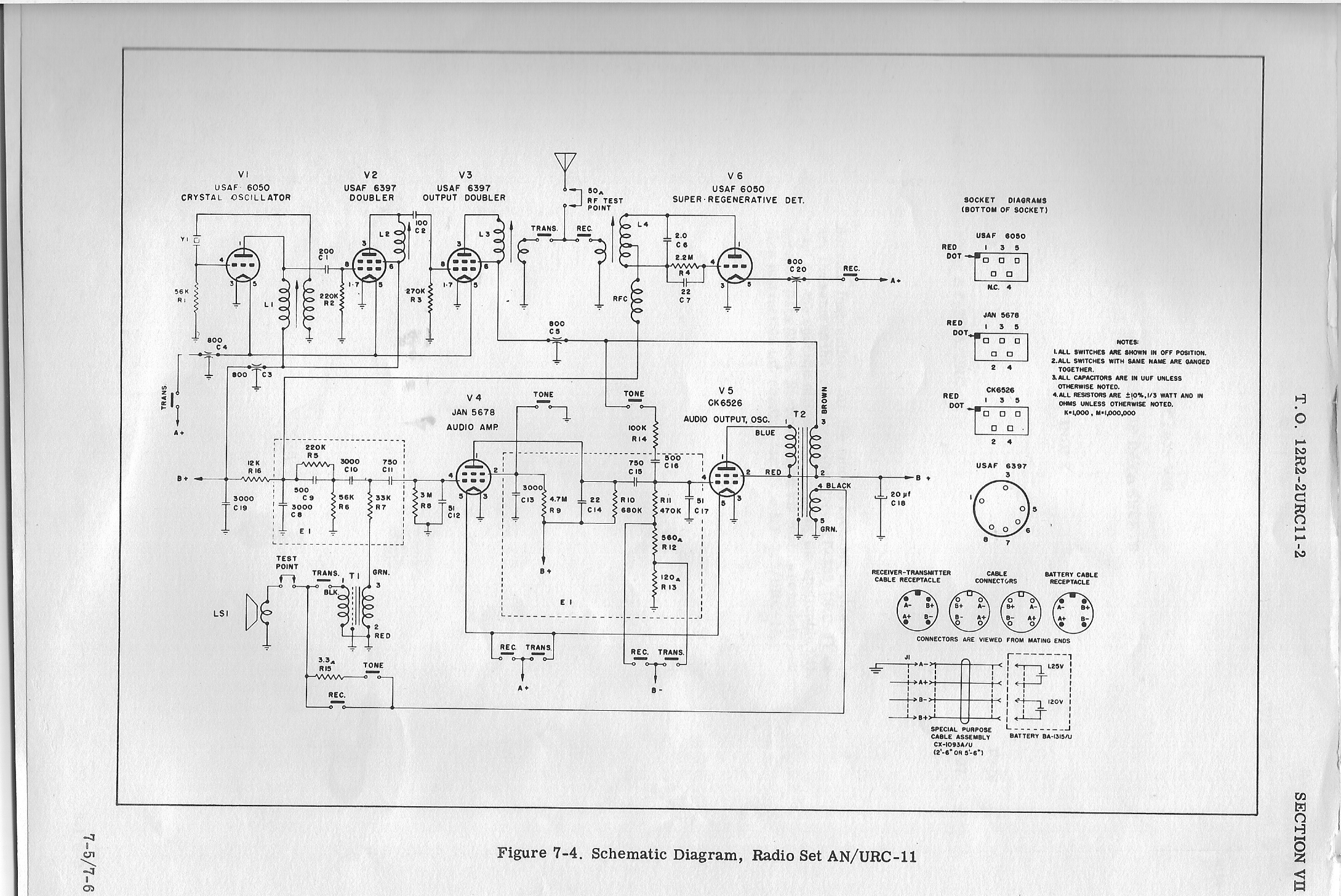
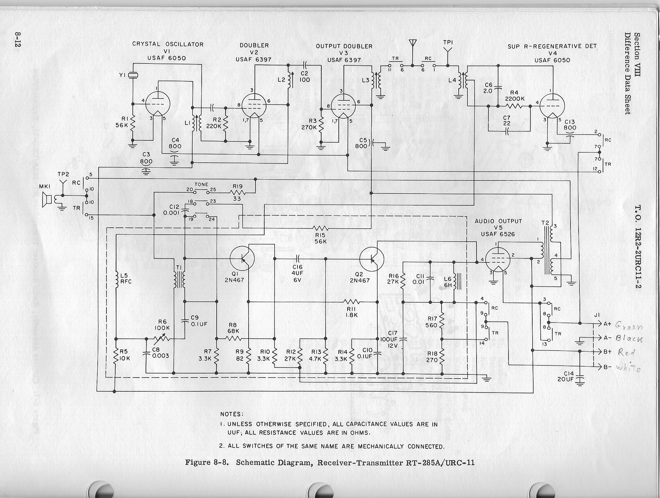
| A couple more drawings: | |
 |
 |
| Skywaves Home Page | |