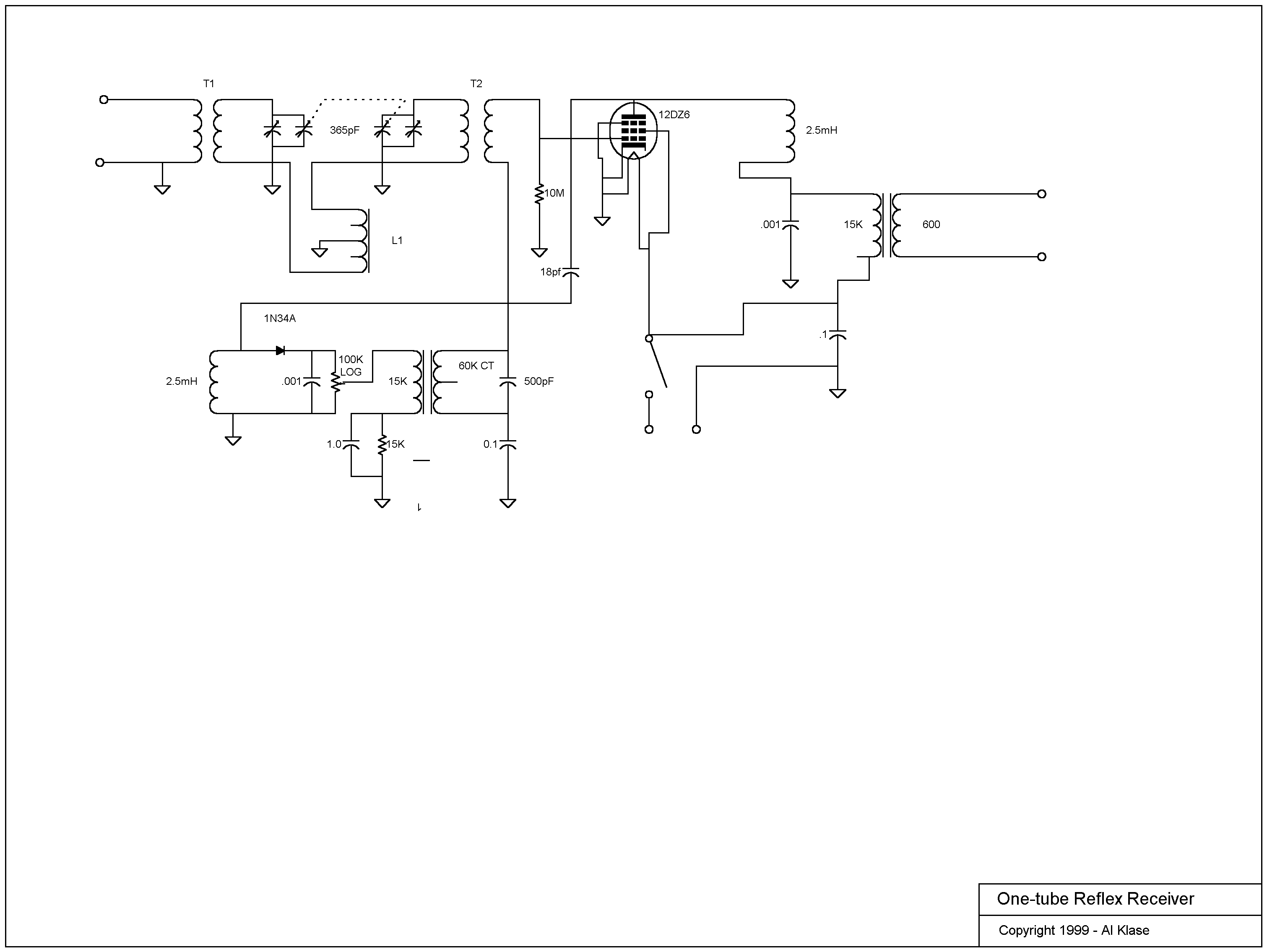

The signals from the antenna pass through a double-tuned band-pass filter consisting of T1 and T2 tuned by a dual-section variable capacitor. L1 provides negative mutual inductance between the two tuned circuits to maintain a constant bandwidth of approximately 12KHz across the entire 530 to 1700KHz tuning range.
The secondary of T2 applies the RF signal to the signal grid of the 12DZ6. Amplified RF on the plate of the tube passes through a fixed 500-1700KHz band-pass filter consisting of two 2.5mH inductors and an 18pF capacitor and is applied to the 1N34 detector.
The audio output of the detector is low-pass filtered by a 0.001uF cap to remove residual RF and is applied to the primary of the first audio transformer via the 100K-ohm volume control. (Yes, the radio is sufficiently "hot" to need a volume control.) The transformer provides voltage gain for the audio signal and additional rejection of RF present in the detector output. A 15K resistor bypassed by a 1uF cap in the ground return of the transformer primary ensures that the detector sees a proper DC load under all circumstances to avoid audio distortion.
Audio from the first AF transformer secondary is applied to the grid of the tube through the secondary of T2. Amplified audio on the plate of the tube passes easily through the 2.5mH RF choke and is applied to the primary of the audio output transformer. A 300-ohm secondary impedance was chosen to match an available sound-powered headset to achieve maximum possible acoustic output. This elaboration proved to be overkill.
The 12DZ6 and similar tubes provide much greater gain than was available from the early triodes used in vintage reflex sets. Therefore, a lot of attention needs to be paid to careful grounding and shielding and proper design of the various filter and bypass circuits in order to avoid oscillation. If this radio whistles like a regen, it's not working properly.