By Al Klase
One of the perennial favorites among radio construction projects is the one-tube battery-powered regenerative receiver. If it's equipped with a short-wave coil, signals come rolling in from thousands of miles away. Such a radio require only a handful of parts and a couple hours to build, but here, in the late twentieth century, appropriate high-voltage batteries are getting harder and harder to find.
A solution to this problem comes to us from the 1950's. A line of vacuum tubes was developed for use in auto radios that function happily with just 10 to 12 volts on their plates. These tubes are languishing in tube stashes everywhere, and are available from the usual purveyors for a dollar or two. Get a tube or two, round up a 12-volt gel-cell battery, a 12-Volt wallwart or cast-off computer power supply, and you're in business. Current consumption for a single tube will be about 200mA, mostly for the heater.
The 12-volt tubes have a couple of unusual characteristics. The most important of which is that they operate best with grid-leak bias. The cathode should be grounded, and the grid resistor should be a very high value, e.g. 10 megohms. Also, the screen grid is generally connected directly to B+. Their major shortcoming is that they cannot supply significant amounts of output power, but this is not significant in a set using headphones.
Some appropriate tubes for a 1-tube regen include: 12AC6, 12AF6, 12BL6, 12CX6, 12DZ6, 12EA6, and 12EK6. These are all pentodes with the same "7BK" pinout as the familiar 12BA6. For triodes, try 12AE6, 12AJ6, 12FK6, or 12FM8. These are similar to the 12AT6.
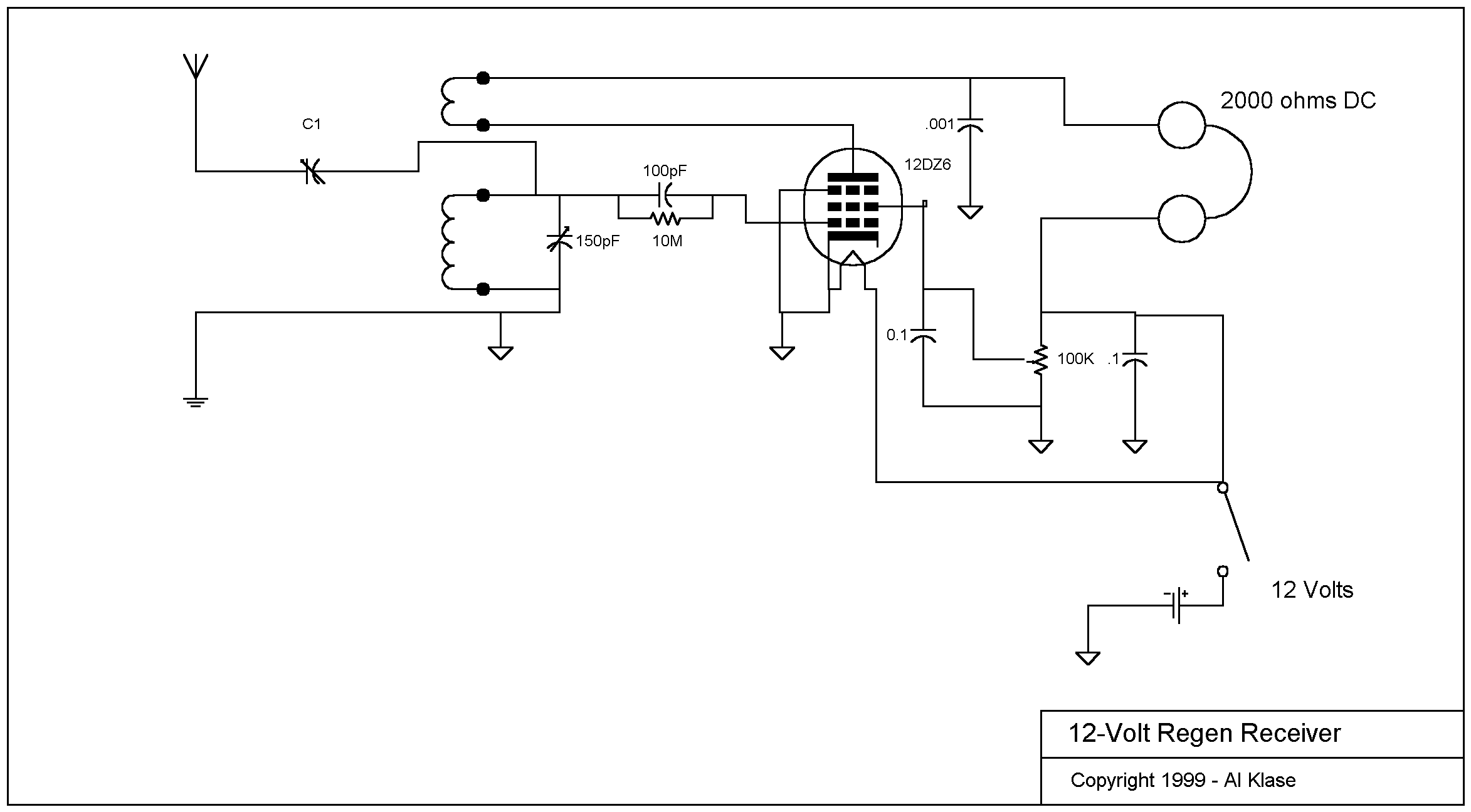
Here's the circuit I've been using. It's pretty much the standard circuit found in all the old books and magazines, so I'm not going to dwell on construction details. The grid-leak resistor has been raised to 10-meg. Regeneration is controlled by varying the screen-grid voltage, but the other schemes should work just a s well.

There are a couple of "old Indian tricks" associated with these circuits: If it won't oscillate, reverse the connections to the tickler coil. If the set goes quickly from no regeneration to a loud squeal, remove some turns from the tickler. The antenna coupling capacitor, C1, is very important for proper operation. It should be variable. About 10pF maximum capacity is about right for short-wave operation. 50pF, or so, is needed for the broadcast band. This control allows you to loosen the antenna coupling if (when) the set won't oscillate.