Last update: 31 July 2020.
A lot of this material was extracted from:
History of Communications-Electronics in the United States Navy
Captain L. S. Howeth, USN (Retired)
Available at: https://archive.org/details/historyofcommuni00howe
SE 143 Manual
SE 1220 Manual
SE 1420 Manual
IP 501A Manual
Also, take a look at Nick Englands "Navy Pre-war SE (Steam Engineering) Receivers"
s
A lot of this material was extracted from:
History of Communications-Electronics in the United States Navy
Captain L. S. Howeth, USN (Retired)
Available at: https://archive.org/details/historyofcommuni00howe
|
History
Radio communications attracted the interest of the Navy, for obvious reasons, very early on. For the moment, I'm going to ignore everything before about 1909 when crystal detectors replace coherers, magnetic detectors, etc. |
|
| In
the beginning receivers were just coherer detectors connected directly
to the antenna-ground system. There was no tuning except for the
resonance of the antenna system. Oliver Lodge assisted Marconi in the development of the syntonic (tuned) system covered by the "Four Sevens" patent. |
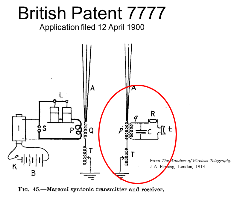 |
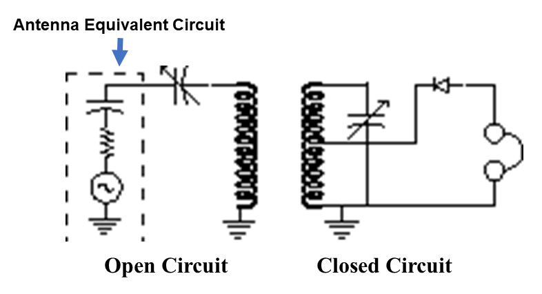 Lodge's receiver incorporated two tuned circuits. The "open circuit" achieves a conjugated match to the antenna, allowing maximum energy transfer. The "closed circuit" adds additional selectivity and matching to the detector This would become the standard architecture for most communications receivers of the wireless era. |
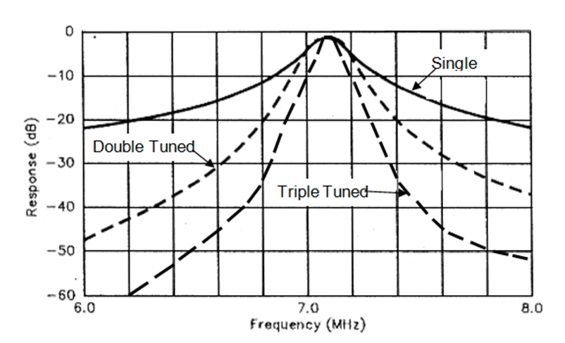 The response of cascades tuned circuits adds algebraically. |
 |
|
|
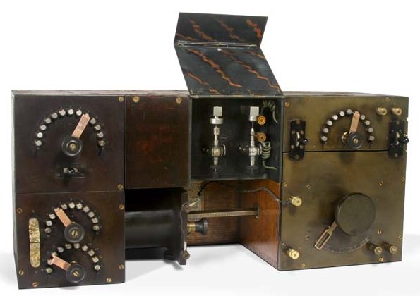
WIRELESS SPECIALTY APPARATUS CO. IP 76 |
|
 |
|
|
The Continuous-Wave Revolution |
|
|
SPARK
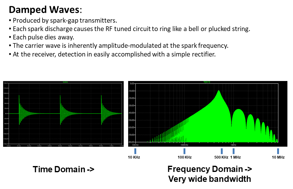 |
CW
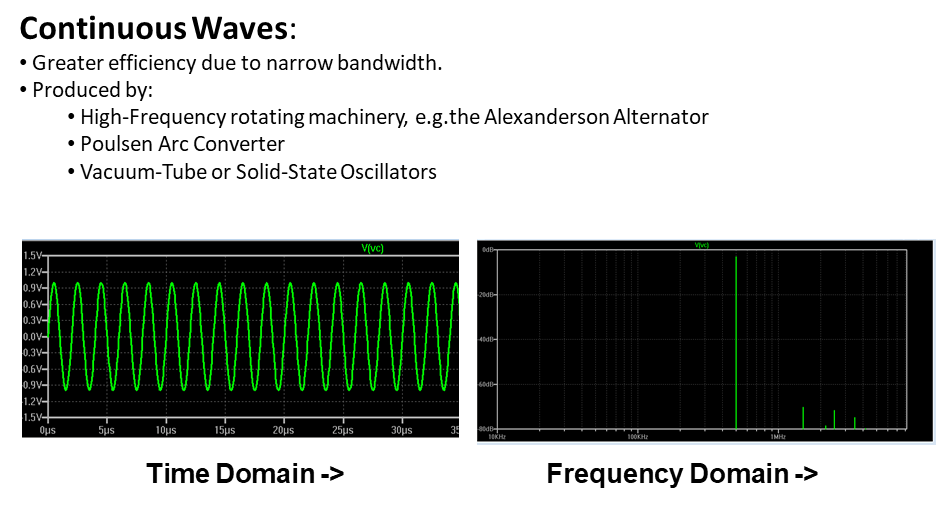 |
 |
|
 Th
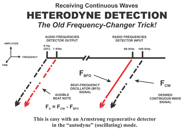
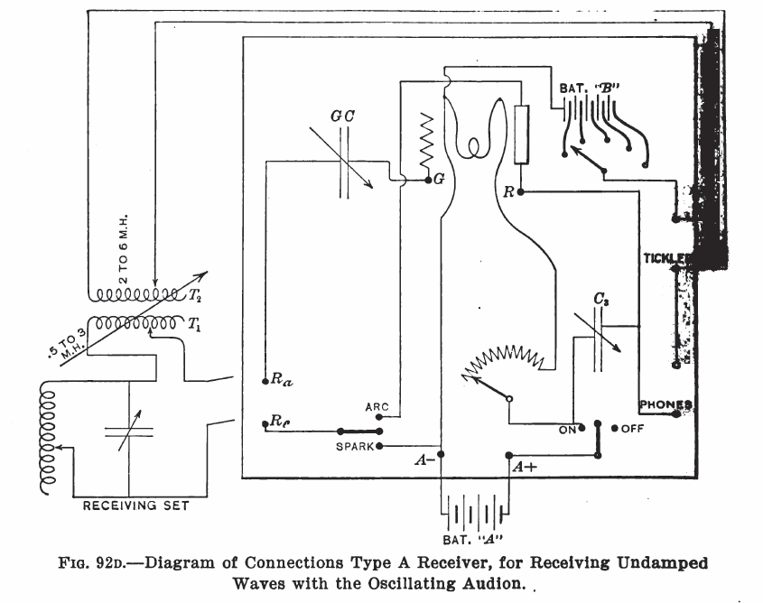
DeForest "Ultraudion" circuit, inspired by Armstrong's
regenerative patent provided a means of heterodyne detection for CW
reception. Various external audion control boxes would be used
until the development of the SE-1420 receiver.
|
|
|
Much
of the following development work was carried on at the Washington (DC)
Navy Yard. This facility was responsible for receivers,
detectors, amplifiers, frequency-meters, and transformers.
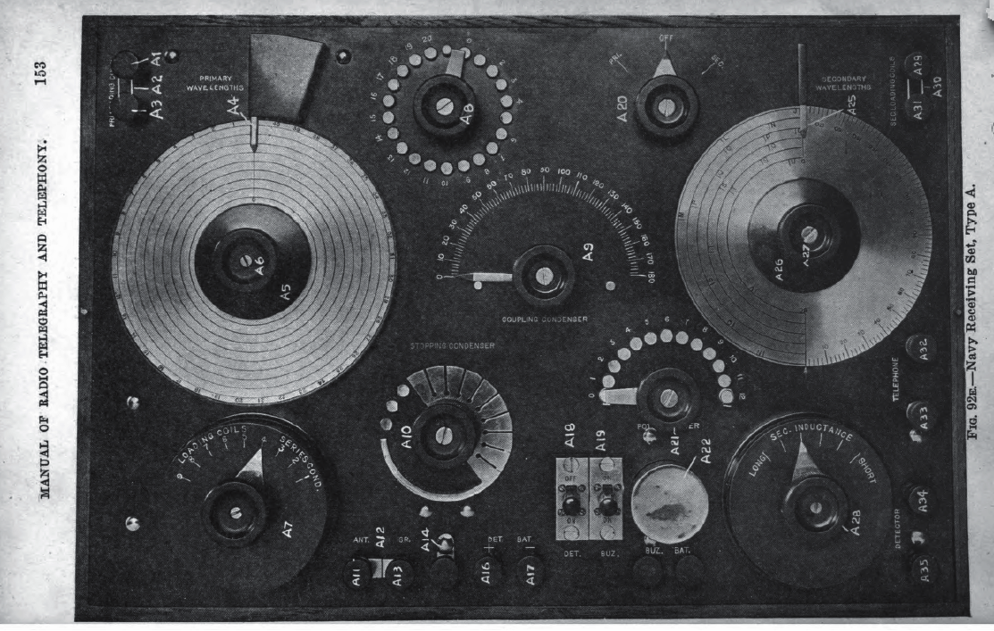
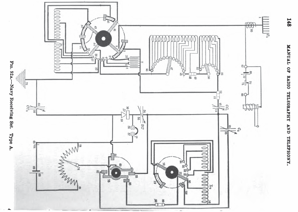
Navy Type A, B, and C Receivers |
|
| Origin of the tickler coil in regenerative receivers Dr. Louis Cohen who, while associated with the National Electric Signaling Co., had worked with Dr. Austin in the formulation of the Austin-Cohen empirical formula, had devised a new means of coupling, utilizing condensers in lieu of the induction coils used by Marconi. The Navy obtained the right to the use of the Cohen patents, and procured his temporary services to assist in the design of receivers.' Howeth, Chapter XVII, p213-214 |
The Navy was attempting to stay clear of some of the existing regenarative patents. "The Cohen method was used. This consisted of coupling and a modified
type of feedback circuit, with a coil in the plate circuit for the
purpose of making the vacuum tube oscillate. To avoid the use of the
term "feed-back," Clark termed it "a 'tickler' because it tickles the
audion and makes it quiver." Even though the tickler feedback circuit is often called the Armstrong oscillator, it does not appear in Armstrong's patents in this exact form. |
|
 |
 |
 |
|
SE-95 and SE-143 (IP-500) |
|
 Excellent pix here: http://online.sfsu.edu/hl/IP500.html |
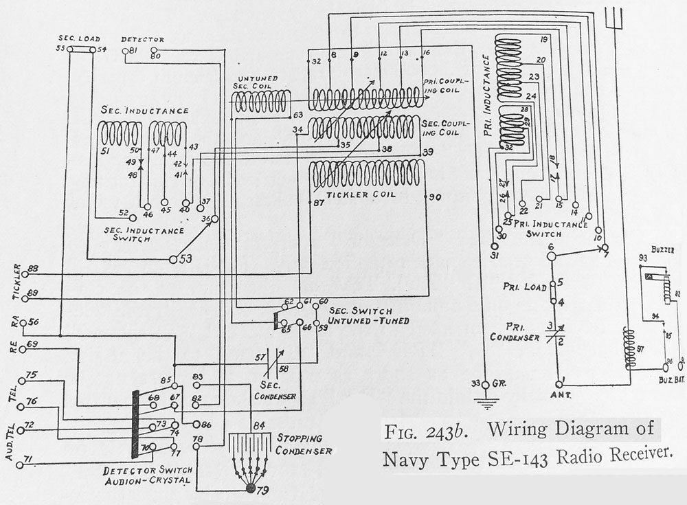 |
Development of SE 143 Howeth, Chapter XX "Receiving Equipment" p 254 SE 143 Manual |
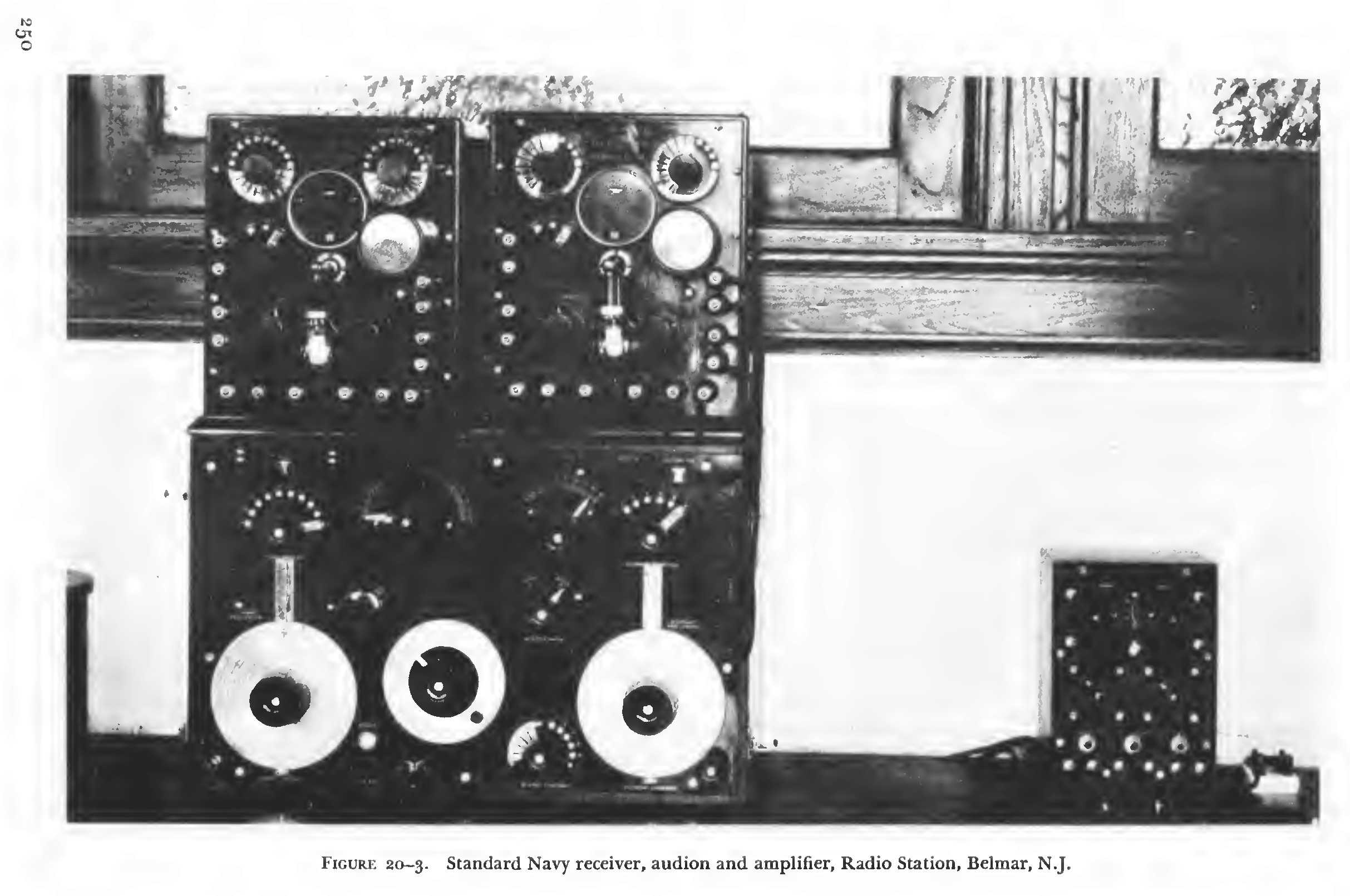 Personal tie-in: I work at The Radio Technology Museum located at the former Marconi Belmar Station, and we have some of this equipment on display. |
|
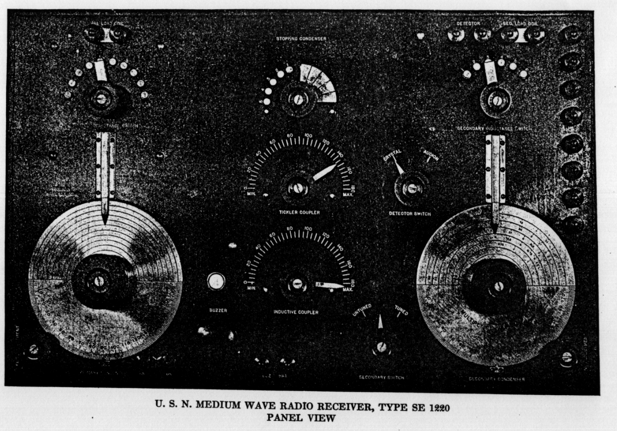
SE-1220 |
|
|
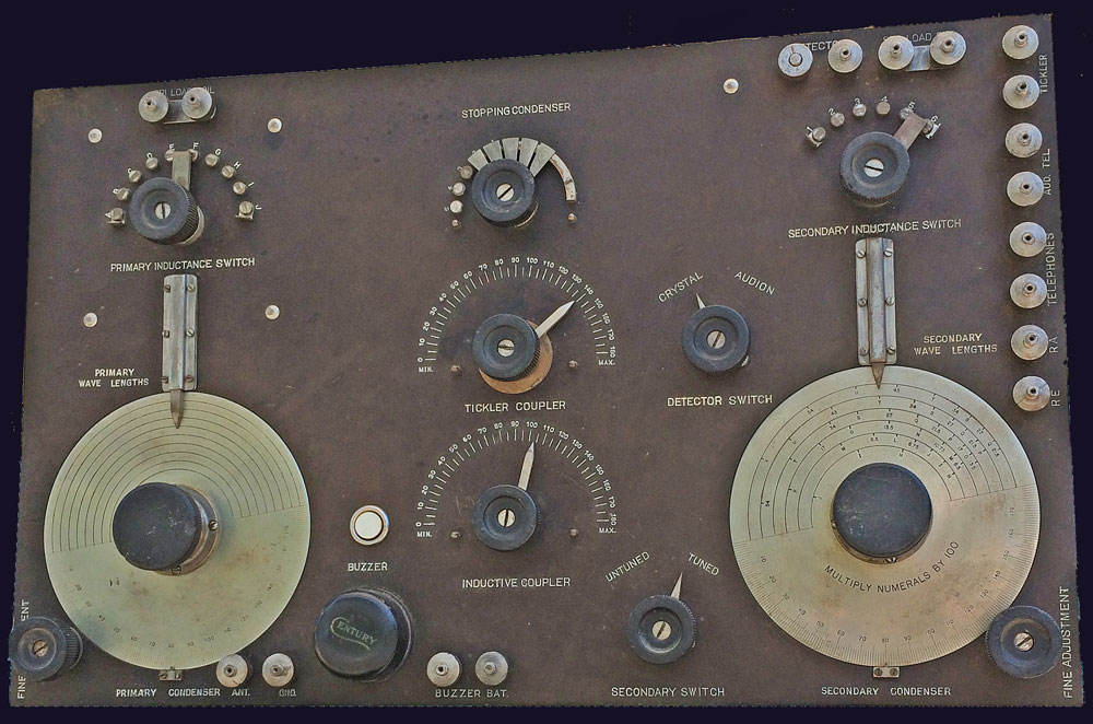
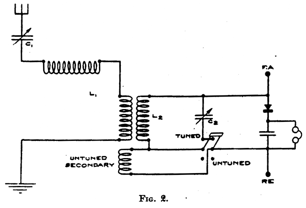 Untuned secondary provides a "standby" function for quick, broad tuning. |
|
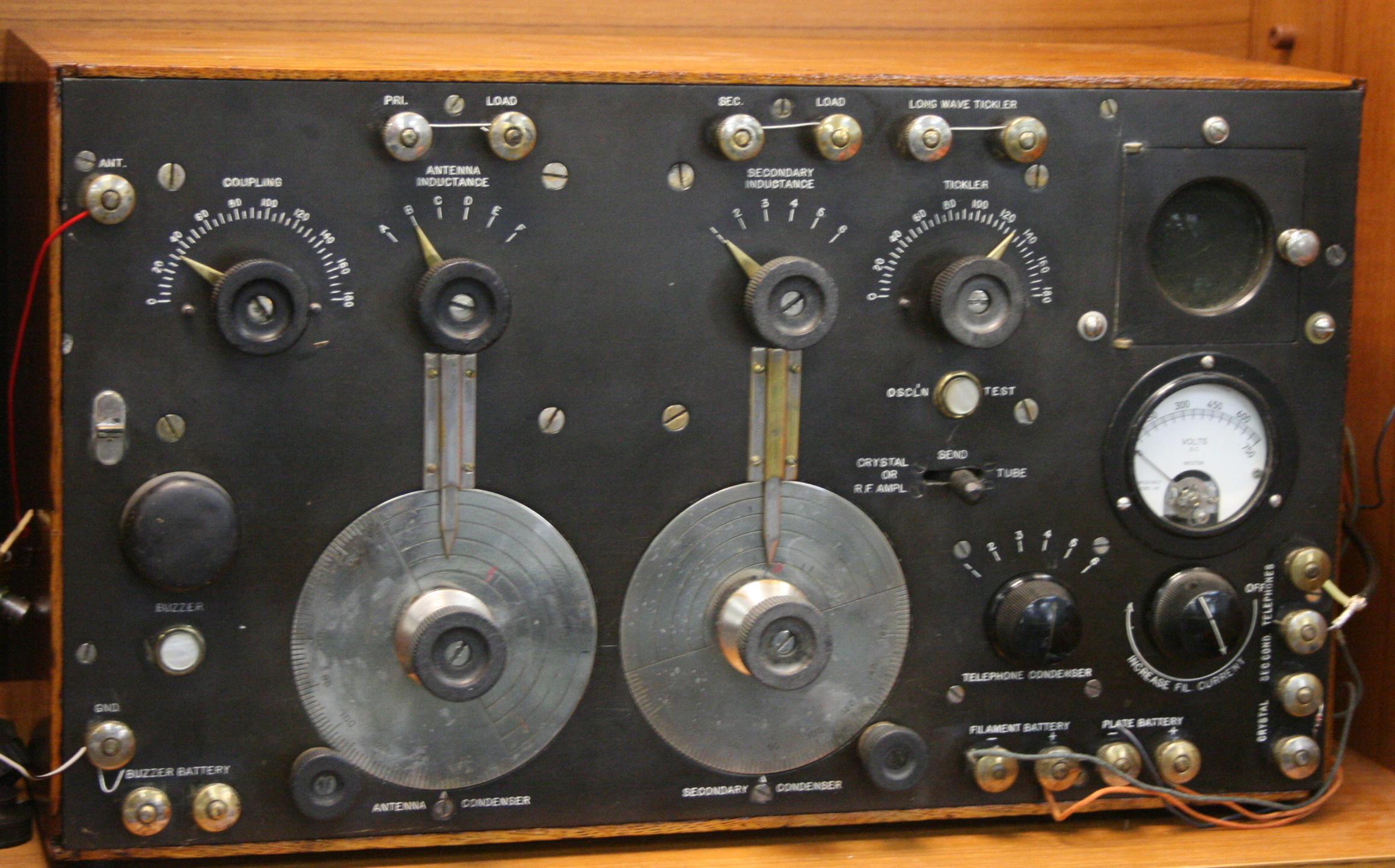
SE-1420 (IP-501) |
|
 |
|
SE 143 Manual
SE 1220 Manual
SE 1420 Manual
IP 501A Manual
Also, take a look at Nick Englands "Navy Pre-war SE (Steam Engineering) Receivers"
s