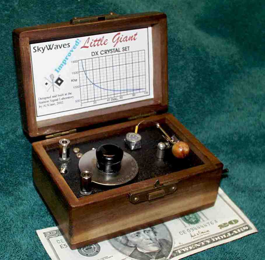
| Schematically, there's
nothing to it: A 365pF cap, a 1N34, a 2K-ohm (DC) headset,
and the transformer. |
|
|
This is actually a double
tuned circuit. The primary is self resonate at about 400 Khz,
tightly coupled to the secondary, and tuned only by the antenna
capacity. The rejection of the primary and secondary add to give
rejection of greater than 50 dB above 5 MHz. The set uses only one
variable capacitor, and has no coupling adjustments or tap switches.
|
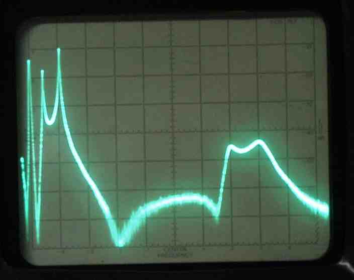
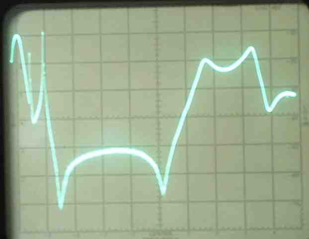
Because there is both
inductive and capacitive coupling between the primary and secondary
winding, phasing is important. Improper phasing will result in
this sort of response. (In this case, right in the 40 -meter band!) If
you hear shortwave, reverse the connections to the primary, or flip the
coil over.
|
|
 |
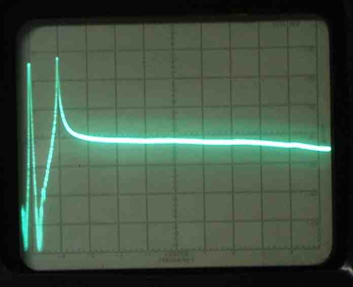
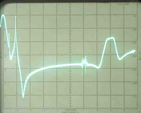
The above data were taken
with the FET probe attached to the top of the secondary tank. I
was assuming that the detector, on the center tap, was seeing a similar
signal. (Years, ago my football coach warned what might happen if
one were ASS-U-ME things.) The first night I tested the set,
short-wave propagation must have been poor. Things seemed to work
well, and I published this page. The following night, I had 40 and
49 meter signals all over the place. The frequency response, measured
right at the detector, looked like this. (Left)
|
|
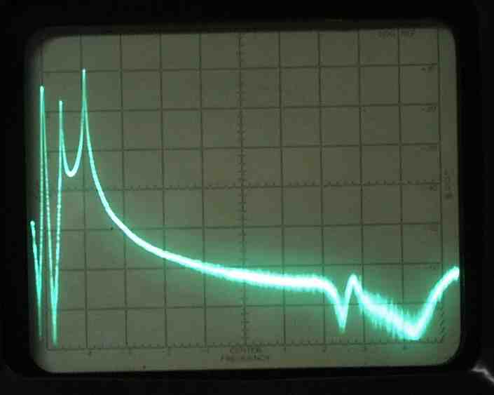
The simple expedient of applying
a Faraday shield to the primary winding achieves reasonable shortwave
rejection. The bump at 8MHz could be a problem if in wanders into
one of the adjacent SW broadcast bands. The "grass" around the 6
MHz line is actual short-waves signals leaking into my test setup
without the benefit of an antenna. (About 23:00 local time.)
|
|
|
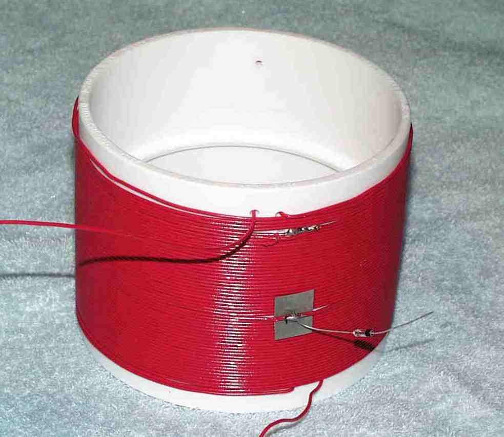
Just as radio stations are
defined by their antennas, radio receivers are defined by their
coils. This one comes from Home Depot. The form is a 4"
styrene pipe coupling. The wire started out as two-conductor #20
"thermostat wire." It's untinned solid copper. they make you
buy 500 feet, so there's enough for 5 or 6 radios. The secondary
is 55 turns tapped near the middle. (25 turns in this case.)
|
| The primary is 75 turns of
the same wire scramble wound around a 12-ounce beverage can, and tied to
keep it neat. |
|
|
The primary is wrapped in
aluminum foil. The first couple of inches of foil are wrapped in
electrical tape.
|
The end of the foil wrapping
overlapps the beginning by about an inch. The tape prevents
electrical contact between the two ends of the foil shield. If
this insulation were not there, the foil would constitute a shorted turn
in the coil, and destroy it's inductive characteristics.
This Faraday shield keeps the electrostatic field inside, but allows
the magnetic field to couple to the secondary.
|
|
|
The primary sits in the
bottom (ground end) of the secondary. The objective is to maximize
inductive coupling while limiting capacitive coupling. (I'll ad an
updated picture, with the shielded primary, soon.)
I can't take credit for this design. This is how input coils for
early tube radios were constructed when energy transfer was still
important.
|
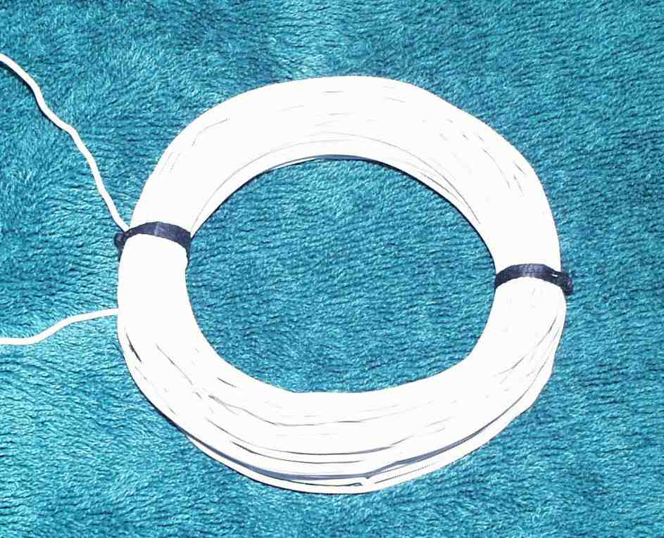
As I mentioned above, I started
out making these transformers on ferrite rods. Details will vary
with the rod material, wire gage, etc. The one at the right is on
a 3/8" rod salvaged from a transistor radio. The white plastic is
hobby shop material, and cuts and glues nicely. The primary, in
the bobbin, should be about 120% of the secondary turns count. The
ferrite core provides tighter coupling than the air-core transformer,
and the small size and physical arrangement of the windings control
capacitive coupling, so the Faraday shield is not needed.
|
|
|
This circuit can make small
sets worthwhile.
|