|
This radio is the result of approximately ten years of sporadic research and experimentation with crystal sets from an engineering perspective. Serious professional development of passive receivers virtually ended with the introduction of reliable vacuum tubes. My conclusions are really pretty straight forward: One needs to pay attention to proper impedance matching at each point in the circuit to assure maximum signal transfer. Multiple tuned circuits with variable coupling allow the operator to trade sensitivity for selectivity. Lastly, a high performance headset can easily be fifty times (17 dB) more sensitive than the instruments usually employed. |
THE CIRCUIT
Basically, the “hookup” is a classic two-circuit tuner with variable coupling between the primary (antenna) and secondary (detector) tuned circuits. This is essentially the same architecture used to great effect in the communication receivers of the wireless era. This circuit was almost never used in commercial broadcast crystal sets because of its high parts count resulting in high price.
The primary or antenna circuit consists of inductor L1 and variable capacitor C1. Switch S1 allows the primary circuit to be used either in series or parallel with the antenna and ground connection. The series connection in normally employed, while the parallel arrangement is helpful with shorter antennas. L1 is tapped via switch S2 to provide a range of inductance values.
The secondary or detector circuit comprises inductor L3 and variable capacitor C2. Tapped inductor L2 is in series with the ground returns of both the primary and secondary circuits, and provides a variable mutual inductance which controls the coupling between the two circuits. This feature allows the operator to trade off signal transfer for increased selectivity. The effect is fundamentally the same a achieved with the telescoping coils of the classic “loose coupler”.
The detector is connected to the high-impedance point at the junction of L3 and C2. This applies the maximum available voltage to the detector to help overcome it’s forward junction drop. Although this is the “usual” connection in many sets, it is often counter-productive as the relatively low impedance (10K ohms) of the ubiquitous 2000 ohm headset unduly loads the tuned circuit compromising both signal strength and selectivity. In this set, the detector load is the 100K ohm primary of audio transformer T1. Switch S4 selects either the “external” crystal detector or the “internal” germanium diode.
T1’s low impedance secondary (600 ohms) provides
optimal coupling to the extremely sensitive headset included with this
radio. Switch S5 may be used to select a medium-high impedance output
for use with more conventional headsets.
In a double tuned receiver, it can be difficult to find a sensitive
spot on the crystal when proper tuning of the primary and secondary has
yet to be achieved. The buzzer circuit provides a broadband RF signal
to allow adjustment of the detector in the absence of a tuned station.
THE COMPONENTS
A conscious effort was made to use commercial-quality US-made vintage components wherever possible. The wafer switches are ceramic units with silver plated contacts, the variable capacitors are high-end Hammarlunds, the tuning knobs and binding posts are from James Millen, the toggle switches are Cutler-Hammer, the phone jack is from Switchcraft and the audio transformer is a UTC A-12. Even the buzzer is a Western Electric “KS” spec. part. One notable exception is the coils, these are wound on modern ferrite cores to provide optimum performance in a reasonable space.
The headset was assembled from a vintage headband and sound-powered telephone elements from a WWII TS-10 handset. It is as sensitive as any I’ve encountered.
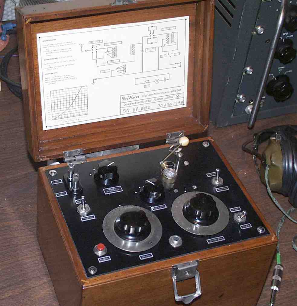
CONSTRUCTION
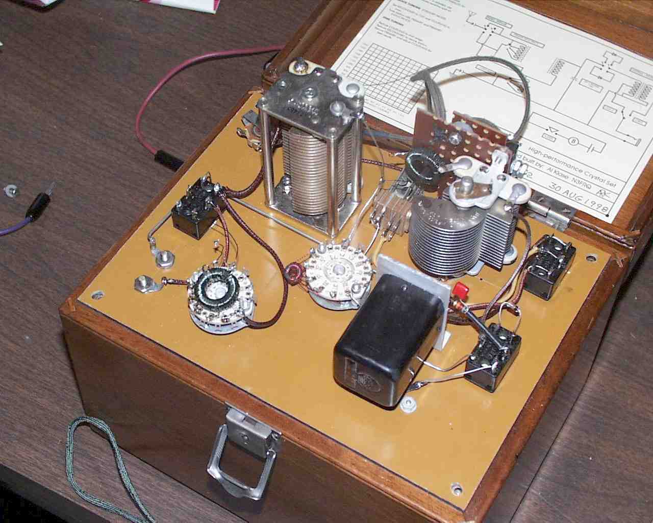
The radio is assembled in an walnut box with a leather carrying handle that once housed a Leeds and Northrup Wheatstone bridge. The bulk of the components are mounted to the Bakelite front panel. Construction technique is best described as 1950’s “model shop”, and is much nicer than an average homebrew set or engineering-lab prototype.
OPERATION
Connect antenna, ground and headset. Select
SERIES for long antennas PARALLEL for short.
If the EXTERNAL detector is selected, activate the BUZZER while
manipulating the catswisker to locate a sensitive spot on the crystal.
To easily locate strong signals, set the SECONDARY capacitor to 100 and COUPLING to maximum (fully clockwise). Tune the set with the PRIMARY capacitor and PRIMARY INDUCTANCE. With this setup, the inductance L3 acts as an untuned secondary to L1. This was known as the “standby” mode in the classic marine wireless receivers.
To take full advantage of the available sensitivity and selectivity, reduce the COUPLING control to midrange and reduce the SECONDARY capacitor to retune the station. Then, adjust the PRIMARY and COUPLING controls for best results. Tuning a receiver of this sort across the band is definitely a two-hand affair. It’s sometimes helpful to rock one knob back and forth while slowly tuning the other.
The tuning of the secondary circuit is fairly repeatable if the coupling is kept light. The tuning chart inside the lid can be used to set the secondary to a desired frequency. It’s calibration is based on position 2 (from the left) of the coupling switch.
COIL DETAILS
The coils are wound on ferrite toroid cores from Amidon associates. L1 is 75 turns of #26 enameled wire on an FT-82-61 core tapped every 15 turns. Inductance is approximately 400 uH maximum. L2 is 25 turns of #30 on an FT-37-61 core tapped at 3, 10, 15, and 20 turns. Inductance is approximately 35 uH maximum. L3 is 68 turns of #26 on an FT-82-61 core. Inductance is approximately 290 uH.